This tutorial is part 3 of a series. View part 1 here.
And the end of part 2 we had roadside objects drawn using scaled sprites and sections of the map.
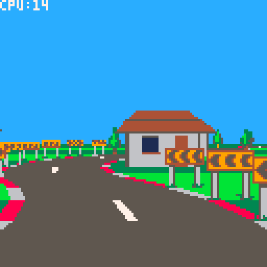
Everything so far has been flat, so in this tutorial we will add some hills and valleys.
This will require solving some overlap issues which we will solve using a clip rectangle "trick", which will in turn set us up nicely for implementing tunnels - so we'll do that too.
Defining the pitch
First we'll define the pitch of each corner with a field called "pi" (not to be mistaken for the Greek letter and mathematical constant).
road={
 {ct=10,tu=0,bgl=bg_tree,bgr=bg_tree},
 {ct=6,tu=-.25,bgl=bg_tree,bgr=bg_sign},
 {ct=8,tu=0,pi=-.75,bgl=bg_tree,bgr=bg_tree},
 {ct=4,tu=.375,bgl=bg_sign,bgr=bg_tree},
 {ct=10,tu=0.05,pi=.75,bgl=bg_tree},
 {ct=4,tu=0,bgl=bg_tree,bgr=bg_tree},
 {ct=5,tu=-.25,bgl=bg_tree,bgr=bg_sign},
 {ct=15,tu=0,pi=-.5,bgc=bg_beams},
 {ct=12,tu=0,bgl=bg_house,bgr=bg_house},
 {ct=8,tu=-.5,bgl=bg_house,bgr=bg_sign},
 {ct=8,tu=.5,bgl=bg_sign,bgr=bg_house},
} |
This will define the gradient at the start of each corner. So a "pitch" of 1 means the ground rises 1 unit for every unit it advances forward - a 45 degree incline. Likewise -1 would be a 45 degree decline. And 0 is of course level.
For brevity we've made the pitch optional - it will default to 0 if not supplied.
To make the hills and valleys smooth the pitch will smoothly interpolate between values across each corner. We will calculate the delta to add to the pitch for each segment in the _init() method:
-- calculate the change in pitch -- per segment for each corner. for i=1,#road do local corner=road[i] local pi=corner.pi or 0 local nextpi=road[i%#road+1].pi or 0 corner.dpi=(nextpi-pi)/corner.ct corner.pi=pi end |
The pitch delta is stored in field "dpi" (not to be confused with "dots per inch" - naming stuff is hard).
Drawing
The pitch affects the vertical direction of the road as it is drawn. We actually already have a "yd" variable which is added to the y coordinate after each segment is drawn. It's just that until now the yd has always been 0, so the ground has always been flat. Now we can use it to create the hills and valleys.
First we calculate the initial value at the start of _draw()
-- direction local camang=camz*road[camcnr].tu local xd=-camang local yd=road[camcnr].pi+road[camcnr].dpi*(camseg-1) local zd=1 |
This is the start value "pi" plus the delta "dpi" added for every segment the camera has traversed along the corner.
Then we add "dpi" to the "yd" after each segment is drawn, similar to how we've added the turn "tu" to "xd":
-- turn and pitch xd+=road[cnr].tu yd+=road[cnr].dpi |
This is all we need to give the road a smooth rising and falling effect.
A note on camera movement
It's worth pointing out that the camera automatically follows the shape of the hills and valleys smoothly, without us having to write any specific code.
This works, because the camera position is skewed in the direction of the segment it is on. Back in tutorial one we implemented the skew function like this:
function skew(x,y,z,xd,yd) return x+z*xd,y+z*yd,z end |
In particular the "y+z*yd" ensures the camera moves up and down with the shape of the road.
Storing positions "unskewed" and skewing them at draw time has some advantages. Regardless of how the road turns or pitches:
- The ground is always at y=0
- The center of the road is always at x=0
- The sides of the road are always at x=+/-3
This approach will also make implementing AI cars easier later on.
Clipping
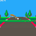
The hills and valleys introduce some obvious overlap issues - sprites visible through hills, far away ground being drawn in front instead of behind.
One approach to fixing this would be to change the road drawing order so that it is back-to-front as well.
This would be a perfectly valid approach (although it would require careful management to incorporate the sprites and road/ground at the same time).
However we're going to use a different approach. We're going to use clipping rectangles to prevent far away road/ground being drawn over near objects.
It will work like this:
- We start with a clipping rectangle covering the whole screen. I.e. nothing is clipped.
- As we draw forward, we move the bottom of the clipping rectangle up so that it does not include the road and ground we have just drawn.
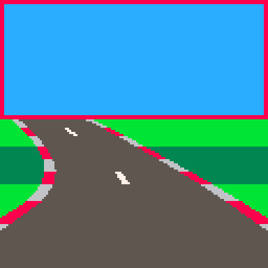
- The clipping rectangle prevents anything drawn further down the road from overlapping with what we've already drawn. Anything that would overlap will simply be clipped away.
The advantage of this method is that we can continue drawing the road as we walk forward along it. We don't have to change the algorithm too much.
It also reduces overdraw, which was important back-in-the-day on platforms that were fill-rate limited. Pico-8 drawing is fast enough that it doesn't really matter though.
To start with we define the initial clip region before the main drawing loop:
 -- current clip region
 local clp={0,0,128,128}
clip() |
The "clp" array defines the left, top, right and bottom values in that order.
We reduce the clip region after drawing each segment, immediately after adding the background sprites (for reasons we'll see later):
-- reduce clip region clp[4]=min(clp[4],ceil(py)) setclip(clp) |
The "min" function ensures that the bottom of the rectangle only ever moves up, which is important for drawing crests of hills correctly.
"setclip" is simply a helper function that sets the Pico-8 clip region for drawing:
function setclip(clp) clip(clp[1],clp[2],clp[3]-clp[1],clp[4]-clp[2]) end |
Putting this together we get:
Clipping sprites
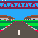
The hills are no longer see through, but now the background sprites are not being drawn correctly. The problem is the sprites are being drawn after the road, when the clipping rectangle has been reduced to cover just the sky. We could reset the clipping rectangle to cover the whole screen before drawing the sprites, which would improve things, but sprites would still be visible through the hills.
What we really need to do is draw each sprite using the clipping rectangle that was active when its segment was drawn, which we can do by storing a copy of the clip rectangle in the sprites array.
We'll add a "clp" parameter to addbgsprite:
function addbgsprite(sp,sumct,bg,side,px,py,scale,clp)

 ...

 -- add to sprite array
 add(sp,{
  x=px,y=py,w=w,h=h,
  img=bg.img,
  mp=bg.mp,
  flp=flp,
  clp={clp[1],clp[2],clp[3],clp[4]}
 })
end |
It's important that we create a new array and copy each of the "clp" fields individually, so that we get a snapshot of the "clp" array at that point. Referencing "clp" directly would not work, because "clp" changes as the road is drawn.
Now we update the calls in the main drawing loop to pass in the clipping rectangle:
-- add background sprites addbgsprite(sp,sumct,road[cnr].bgl,-1,px,py,scale,clp) addbgsprite(sp,sumct,road[cnr].bgr, 1,px,py,scale,clp) addbgsprite(sp,sumct,road[cnr].bgc, 0,px,py,scale,clp) |
Finally we apply the clipping rectangle in drawbgsprite:
function drawbgsprite(s) setclip(s.clp) ... |
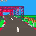
With this in place we should have hills and valleys drawn correctly, including the background sprites.
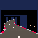
Tunnels
For the last part of this tutorial we will implement basic tunnels. Tunnels give racing games a cool change of environment and they're just fun to drive through.
And with the clipping rectangle logic is in place they're reasonably straightforward to implement.
It's essentially an extension of the clipping logic used for the ground. But now we also reduce the top of the clipping rectangle as we draw the tunnel ceiling, and the left and right sides as we draw the tunnel walls.
We'll start by defining the tunnel in our road:
road={
 {ct=10,tu=0,bgl=bg_tree,bgr=bg_tree},
 {ct=6,tu=-.25,bgl=bg_tree,bgr=bg_sign},
 {ct=8,tu=0,pi=-.75,bgl=bg_tree,bgr=bg_tree},

 {ct=8,tu=0,tnl=true},
 {ct=4,tu=0,tnl=true},
 {ct=8,tu=0,pi=.75,tnl=true},
 {ct=8,tu=-.5,pi=.75,tnl=true},
 {ct=4,tu=0,tnl=true},
 {ct=8,tu=.5,tnl=true},
 {ct=4,tu=0,pi=-.5,tnl=true},
 {ct=8,tu=0,pi=-.5,tnl=true},

 {ct=4,tu=.375,bgl=bg_sign,bgr=bg_tree},
 {ct=10,tu=0.05,pi=.75,bgl=bg_tree},
 {ct=4,tu=0,bgl=bg_tree,bgr=bg_tree},
 {ct=5,tu=-.25,bgl=bg_tree,bgr=bg_sign},
 {ct=15,tu=0,pi=-.5,bgc=bg_beams},
 {ct=12,tu=0,bgl=bg_house,bgr=bg_house},
 {ct=8,tu=-.5,bgl=bg_house,bgr=bg_sign},
 {ct=8,tu=.5,bgl=bg_sign,bgr=bg_house},
} |
Tunnel corners are denoted by "tnl=true".
I've placed the tunnel section towards the start of the road so that it's quicker to get to for testing and debugging. (It can be moved later once everything is working correctly).
Tunnel front face
Next we'll draw the tunnel face.
We need to detect the first corner tunnel ("tnl" is set to true) where the previous corner was not a tunnel, which we can do by tracking the tunnel flag for the current corner, and the previous corner.
We set the initial value of the previous tunnel flag before the main drawing loop:
-- previous tunnel flag local ptnl=road[cnr].tnl |
Strictly speaking this should be set to the "tnl" property of the previous segment, but it doesn't actually make any noticeable difference for our purposes.
Inside the main loop we compare it with the current segment's tunnel flag, and draw the tunnel face at the start of the tunnel:
-- draw tunnel face local tnl=road[cnr].tnl if tnl and not ptnl then drawtunnelface(ppx,ppy,pscale) end |
Note that the tunnel face will be drawn at the start of the current segment. This means we must use the previous cursor position (ppx, ppy, pscale), as cursor positions are for the end of their segment.
We also need to copy "tnl" to "ptnl" just before the loop ends, so that "ptnl" is set correctly for the next segment:
-- track previous projected position ppx,ppy,pscale=px,py,scale ptnl=tnl |
We will draw the tunnel face by drawing rectangles around the mouth of the tunnel.
We'll start by creating a helper function that takes the projected road position and calculates a rectangle describing the tunnel floor, ceiling and walls.
function gettunnelrect(px,py,scale) local w,h=6.4*scale,4*scale local x1=ceil(px-w/2) local y1=ceil(py-h) local x2=ceil(px+w/2) local y2=ceil(py) return x1,y1,x2,y2 end |
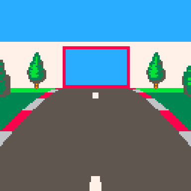
The red rectangle is the "tunnel rectangle". I.e. the mouth of the tunnel.
We're allowing 6.4 units of width for the road, rather than 6, because the red and white shoulder things stick out another 0.2 units each way.
The tunnel will be 4 units high, which is low enough to make the tunnel feel claustrophobic but high enough to be above the camera.
Using this we can implement drawtunnelface:
function drawtunnelface(px,py,scale) -- tunnel mouth local x1,y1,x2,y2=gettunnelrect(px,py,scale) -- tunnel wall top local wh=4.5*scale local wy=ceil(py-wh) -- draw faces if(y1>0)rectfill(0,wy,128,y1-1,7) if(x1>0)rectfill(0,y1,x1-1,y2-1,7) if(x2<128)rectfill(x2,y1,127,y2-1,7) end |
Essentially we're drawing a rectangle that extends from the top of the facing wall down to the top of the tunnel mouth. Then we draw two more rectangles either side of the mouth down to the ground.
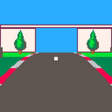
The last thing we need to do is restrict the clipping rectangle to the tunnel mouth.
We'll create this function to adjust the clipping rectangle:
function cliptotunnel(px,py,scale,clp) local x1,y1,x2,y2=gettunnelrect(px,py,scale) clp[1]=max(clp[1],x1) clp[2]=max(clp[2],y1) clp[3]=min(clp[3],x2) clp[4]=min(clp[4],y2) end |
And update the tunnel face drawing code in the main drawing loop:
-- draw tunnel face local tnl=road[cnr].tnl if tnl and not ptnl then drawtunnelface(ppx,ppy,pscale) cliptotunnel(ppx,ppy,pscale,clp) setclip(clp) end |
Now we should have a front facing tunnel wall:
Tunnel interior
Next we need to draw the tunnel interior. This will consist of the ceiling, walls and road.
First we need to separate the road drawing code from the ground drawing code, so that we can just draw the road when inside the tunnel. We'll move the ground drawing code out into it's own function:
function drawground(y1,y2,sumct) if(flr(y2)<ceil(y1))return -- draw ground local gndcol=3 if((sumct%6)>=3)gndcol=11 rectfill(0,ceil(y1),128,flr(y2),gndcol) end |
And delete the "draw ground" lines from drawroad.
We'll update the drawing code in the main loop to draw the ground or tunnel interior as appropriate, then draw the road:
-- draw ground/tunnel walls local sumct=getsumct(cnr,seg) if tnl then drawtunnelwalls(px,py,scale,ppx,ppy,pscale,sumct) else drawground(py,ppy,sumct) end -- draw road drawroad(px,py,scale,ppx,ppy,pscale,sumct) |
We draw the tunnel walls by comparing the tunnel rectangles at the start and end of the current segment.
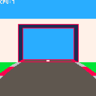
We draw a ceiling rectangle to connect the top of each tunnel rectangle.
Then we draw wall rectangles on each side to connect the left and right sides.
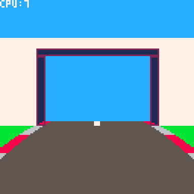
We'll use an alternating colour for effect.
function drawtunnelwalls(px,py,scale,ppx,ppy,pscale,sumct) -- colour local wallcol=0 if(sumct%4<2)wallcol=1 -- draw walls local x1,y1,x2,y2=gettunnelrect(px,py,scale) local px1,py1,px2,py2=gettunnelrect(ppx,ppy,pscale) if(y1>py1)rectfill(px1,py1,px2-1,y1-1,wallcol) if(x1>px1)rectfill(px1,y1,x1-1,py2-1,wallcol) if(x2<px2)rectfill(x2,y1,px2-1,py2-1,wallcol) end |
The final step is to update the reduce-clip-region logic in the main drawing loop to handle tunnels.
-- reduce clip region if tnl then cliptotunnel(px,py,scale,clp) else clp[4]=min(clp[4],ceil(py)) end setclip(clp) |
And this completes our tunnel:
Next steps
This is the end of part 3. In part 4 we'll add some cars to overtake.

You have really snapped on to this, @Mot. :D
Here is your first star for this incarnation.
Now all you need is an in-code road editor for both players and designers.

Thanks.
Actually an editor wouldn't be too difficult. The road data structure isn't that complex.

Let me know if part 4 onwards will be up and running. I am trying to learn Lua, even if my ADHD sees the learning process as too "herculean" to my current intellect.

You've picked a good platform to learn on.
I have the code changes all ready to go for a part 4. I just haven't done the write up yet - been a bit side-tracked by other projects.
Also I wasn't sure how much of a demand there was to go further.

Hey! I'm new with Lua but this will be one of my first projects when i feel more confident, really nice tutorial!
Do you know if it would be too complex to add SpriteStack models? I want to achieve this look
https://twitter.com/chiptune/status/881615357907271681

@equlsa I think I've seen somebody use spritestack sprites in Pico-8, but I don't know how much work it would be. I assume if you can get the sprites loaded in it's just about drawing the slices on top of each other. Drawing them scaled might complicate things a little, but should be doable.

Sorry to grave post but is part 4 coming? And if not, how do I add actual player input?

Yeah, perhaps I should actually finish this.
I had some source code and sprites for the next version, but they got lost/deleted somehow, which threw me off my stride and I never got around to picking it up again.

I would like to make a game where the road doesn't turn by itself, but after several attempts I haven't succeeded. Any advice Mot?
[Please log in to post a comment]


