So, let's say you're building a synthesizer using the serial PCM output and you want a filter. What do?
Well, what I did was follow a link @luchak posted a while ago in the Discord to this SVF filter design by Andrew Simper, Laurent de Soras, and Steffan Diedrichsen. And then get blasted with noise, because a design that works great with double-precision floating-point numbers is not so great with 16b.16b fixed-point PICO-8 numbers.
Edit: I recommend using the code snippet downthread rather than this one.
Now, I'm not good enough at math to prove mathematically that this is stable, but I'm good enough at hacking together testing code to feel confident that, as long as:
- the signal being fed into the filter remains in the range -1 to 1,
- the resonance remains in the range 0 to 1, and
- the cutoff remains in the range 0 to 2756.25 (the Nyquist frequency for PICO-8's 5512.5 Hz PCM output)
...this should produce an output that remains within the range -3 to 3 -3.5 to 3.5 and is usable.
--this is the initialization section; do it outside the sample calculation loop local f_low,f_band=0,0 --these are the filter parameters --I haven't tested changing them while the filter is running but that's what I plan to do, so, here's hoping. local res=0 to 1 local freq=-2.0*sin(cutoff frequency/22050)--sin( 0.5 * cutoff frequency/(2*sampling frequency) ) --after you set freq and res, these two are derived local drive=max(0,.05*res-.0125)--0 for res<0.25, increase linearly to 0.0375 for res=1 local damp=min(2.0*(1.0 - res^0.25), min(2.0, 2.0/freq - freq*0.5)) -- -- -- do the calculations here to generate osc, your signal to be filtered -- -- --2x oversampled filter local f_notch=osc-damp*f_band f_low+=freq*f_band local f_high=f_notch-f_low f_band-=drive*f_band*f_band*f_band--distortion f_band+=freq*f_high--filter local out=(f_notch or f_low or f_high or f_band)>>1--half here... f_notch=osc-damp*f_band f_low+=freq*f_band f_high=f_notch-f_low f_band-=drive*f_band*f_band*f_band--distortion f_band+=freq*f_high--filter out+=(f_notch or f_low or f_high or f_band)>>1--...and half here |
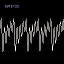
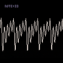
To show it off, here's my current very incomplete version of a button keyboard cart. Same keyboard keys as you use for SFX editor note entry; left-right arrows to change octave. This filter is set up with a cutoff frequency of A5 (880 Hz) and a resonance of 1.

A small change: doing some more testing, it's possible to drive this filter harder than I like for the overdrive settings I suggested. I could not make it break, and I've updated the OP to place the bounds at +/-3.5x input, but for safety's sake, I'd probably pull the drive back a little bit and use:
local drive=max(0, .03*res-.0075)--max drive is 0.0225, which fully saturates at ~3.85 |
which had a peak amplitude just under 4 when driven with a square wave of amplitude 1.
I think the other one will be fine, but given that I made some incorrect assumptions in my testing of the other one, this is the function I'm going to use.

Great sound and I love that I can control the volume by how long I press the key. Makes the keyboard feel very responsive.
What's that background buzz I hear, though? Is that an intended part of the sound? Almost sounds like crackle because not enough samples sent to the buffer at a time, but I'm not sure.
Anyhow, your synth is very cool!

It's entirely possible that not enough samples are being sent - I think different browsers handle their audio buffer differently, and this specific cart is stingy with samples in the name of responsiveness. 551 samples (the current setting) is enough in Firefox and PICO-8 itself in my experience, but 768 (or even 1024 if that doesn't cause issues) might be more robust ... but 551 samples is already an input lag of 100 ms, and that sounds like a lot to me.
I might go ahead and add a toggle between 551 and something bigger, now that I think about it.

Had a thought, gave it some testing: finding stability for the overdrive can be simplified if the cubic saturation calculation is put after the filter step - which makes more sense to me but isn't how the reference implementation I was working from did it.
Anyway, with this one, it looks like any constant value for drive from 0.0001 to 0.0392 should work, emphasis on "should" - for safety's sake, and also because it keeps the amount of amplification tame, I went with 0.02.
--this is the initialization section; do it outside the sample calculation loop local f_low,f_band=0,0 --these are the filter parameters --I haven't tested changing them while the filter is running but that's what I plan to do, so, here's hoping. local res=0 to 1 local freq=-2.0*sin(cutoff frequency/22050)--sin( 0.5 * cutoff frequency/(2*sampling frequency) ) --after you set freq and res, these two are derived local drive=0.02--with amplitude 1 square wave driving, max amplitude for each output is: -- - high pass less than 3.6 -- - low pass less than 3.4 -- - band & notch less than 2.8 local damp=min(2.0*(1.0 - res^0.25), min(2.0, 2.0/freq - freq*0.5)) -- -- -- do the calculations here to generate osc, your signal to be filtered -- -- --2x oversampled filter local f_notch=osc-damp*f_band f_low+=freq*f_band local f_high=f_notch-f_low f_band+=freq*f_high--filter f_band-=drive*f_band*f_band*f_band--distortion local out=(f_notch or f_low or f_high or f_band)>>1--half here... f_notch=osc-damp*f_band f_low+=freq*f_band f_high=f_notch-f_low f_band+=freq*f_high--filter f_band-=drive*f_band*f_band*f_band--distortion out+=(f_notch or f_low or f_high or f_band)>>1--...and half here |
As far as I can tell, this sounds basically the same, but it sounded fine before so I'm happy with that. And the math is simpler.
[Please log in to post a comment]


