Pseudo 3D racing games are fun. They have a cool retro arcade feel, with a good sense of speed, and can run on low end hardware. Plus they're pretty straightforward to implement - and satisfying.
There are lots of different ways to write a pseudo 3D racer, but I'm just going to show you how I do it.
This is the method I used for Loose Gravel, and can render corners, hills, tunnels and background sprites in an efficient manner. It doesn't need any 3D drawing hardware, just basic 2D rectangles, lines, scaled sprites and rectangular clip regions. Pico-8 can do all of these.
Defining the road
The road is made out of "corners" (for our purposes we will call straight bits "corners" as well). Corners need to curve in the direction the road turns, so we will simulate this by building them out of smaller straight "segments".
We can define the track as an array of these corners.
road={
 {ct=10,tu=0},
 {ct=6,tu=-1},
 {ct=8,tu=0},
 {ct=4,tu=1.5},
 {ct=10,tu=0.2},
 {ct=4,tu=0},
 {ct=5,tu=-1},
} |
Each corner has a segment count "ct" and a value indicating how much the direction turns between each segment "tu".
So tu=0 creates a straight piece, tu=1 will turn to the right, -1 left etc.
For simplicity we'll ignore hills and valleys for now.
Drawing the road
We will draw the road by walking a 3D "cursor" along it and drawing the road at each point.
We'll define the cursor like this:
local x,y,z=0,1,1 |
We will start drawing the road slightly in front (z=1) and below (y=1) the camera position.
Note: I use x=right, y=down, z=into the screen as my coordinate system. I find this easiest to work with, having x and y in the same direction as on the screen and keeping z coordinates positive.
The direction of the road is another 3D vector:
local xd,yd,zd=0,0,1 |
So initially the road will point straight forward (zd=1).
The direction will be added to the cursor's 3D position to move from the current segment to the start of the next. To keep the maths simple we're using segments of length 1.
We also need to track which corner and segment we are drawing:
local cnr,seg=1,1 |
The main drawing loop will draw 30 segments of the road from the starting position, as follows:
- Draw the road at the current position
- Move to the next position in 3D space
- Adjust the direction based on how the road turns
- Advance to the next segment (and corner if applicable)
Putting this together, gives us something like this:
Click "code" up above to view the code.
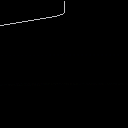
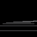
It's just a static boring line for now, but the basic logic is there. I was pretty vague about what "draw the road" means so we're just drawing a line to the x and z coordinates of the "cursor" for now.
We can see that the road goes straight for a bit then turns to the left as it moves down the screen.
We're "adjusting the direction" by adding the turn amount for the current corner to the X coordinate of our direction vector:
xd+=road[cnr].tu |
which means we're actually skewing the road rather than rotating it. This is part of the "pseudo" in our pseudo 3D - the difference is if we were using proper rotation the road would eventually turn around and start coming back towards us - if it turned far enough - whereas with skewing it just keeps stretching out more and more horizontally.
Although less realistic, skewing is much simpler to implement, and means that the road will always face away from the camera, which makes drawing things in the right order a lot simpler. And as long as the corners aren't too sharp it's an acceptable approximation.
Making it 3D
The key making this 3D is called perspective projection.
This converts a 3D coordinate into a 2D screen coordinate. I won't bore you with the mathematics - there are plenty of other places you can find this information if you really want to.
The important thing is the formula, which is:
- px=x*64/z+64
- py=y*64/z+64
This gives a 90 degree field of view (FOV). Replacing the 64 in 64/z with a smaller value would give a wider FOV, or a larger value would give a narrower FOV. We'll stick with 64 however. The +64 moves everything into the center of the screen.
64/z is also a useful value to keep, because it is the scale factor for anything drawn at that position, such as scaled sprites, or the road width. So the project function will return this too:
function project(x,y,z) local scale=64/z return x*scale+64,y*scale+64,scale end |
With this we can replace the line drawing code in the main loop:
-- project local px,py,scale=project(x,y,z) -- draw road local width=3*scale line(px-width,py,px+width,py) |
The projection allows us to draw a horizontal line 6 units wide, scaled appropriately for the 3D position.
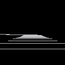
This produces something a little more like looking down a road.
Adding movement
Right now the road is static, because it is always drawn from the same position.
To get the sensation of movement we need to simulate a camera moving down the road, and draw it from the camera's position.
So we'll declare the camera:
camcnr,camseg=1,1 |
And change "cursor" in the _draw() function to start from the camera position:
local cnr,seg=camcnr,camseg |
We can use the same logic to advance the camera to the next segment as we do for the "cursor" when drawing, by moving it out into a function:
function advance(cnr,seg) seg+=1 if seg>road[cnr].ct then seg=1 cnr+=1 if(cnr>#road)cnr=1 end return cnr,seg end |
This advances to the next segment in the corner, and if necessary the next corner in the road, looping around to the first corner if required.
Then we call it from the _draw() function:
-- advance along road cnr,seg=advance(cnr,seg) |
And use it to advance the camera in _update():
function _update() camcnr,camseg=advance(camcnr,camseg) end |
Putting it together we get:
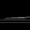
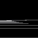
Which sort-of looks like movement, but isn't totally convincing.
The camera is moving one full segment per rendered frame, which means the segment lines are rendered at the same distance each time.
We need to move less than a full segment per rendered frame, which means we need to track the camera position relative to the current segment:
camx,camy,camz=0,0,0 |
Now we can advance the camera by less than a full segment length:
function _update() camz+=0.1 if camz>1 then camz-=1 camcnr,camseg=advance(camcnr,camseg) end end |
Inside _draw() we start drawing relative to the camera position, by subtracting the camera coordinates from the starting coordinates.
local x,y,z=-camx,-camy+1,-camz+1 |
With these changes the forward movement feels more convincing:
But now cornering feels janky.
This is because the camera is always aligned exactly with the segment it is on, so when it moves to the next segment it snaps sharply.
To counter this we need to turn the camera smoothly towards the next segment's angle as it progresses down the current segment. We can compute this angle in _draw() as:
local camang=camz*road[camcnr].tu |
Then subtract it from the initial cursor direction:
local xd,yd,zd=-camang,0,1 |
This gives some improvement:
It's still not 100% though - there's still some horizontal juddering.
This can be a little tricky to understand the cause of.
The gist of it is that by turning the camera, we're skewing the first segment will be rendered. But when we calculate the cursor position relative to the camera, we're using the un-skewed camera offset. So when we draw the road forward again, the part that should pass through the camera point will actually be skewed left or right of it. This makes the camera appear to diverge from the path of the road as it moves towards the end of the segment. It then snaps back into the center when it progresses to the next segment.
To fix this issue we need to first skew the camera position in the "cursor" direction, then calculate the cursor position relative to the skewed camera position.
We'll start by creating a basic skew function:
function skew(x,y,z,xd,yd) return x+z*xd,y+z*yd,z end |
Essentially we're skewing the Z axis from (0,0,1) to (xd,yd,1).
We'll need to re-order the "cursor" setup code in _draw(), so that the direction is calculated first.
I.e. move this bit in front of the initial x,y,z calculation:
-- direction local camang=camz*road[camcnr].tu local xd,yd,zd=-camang,0,1 |
Then we can calculate the skewed camera position:
local cx,cy,cz=skew(camx,camy,camz,xd,yd) |
And calculate the initial "cursor" position relative to the skewed camera:
local x,y,z=-cx,-cy+1,-cz+1 |
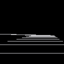
This finally gives us nice smooth camera movement:
This is the core road drawing algorithm for a pseudo 3D racer.
The last step is to simply clean up the rendering so it's not just white lines on black.
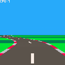
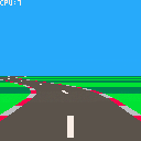
With a little bit of work we can turn it into something like this:
I won't go into too much detail here - you can refer to the cartridge code for specifics - I'll just touch on a few basic points.
To draw the road we need to render a trapezium (also known as a trapezoid). Essentially we're joining the horizontal lines together and filling them in. Pico-8 doesn't have a built in trapezium drawing function, but we can roll our own by stacking 1-pixel high rectangles.
We use alternating colours to communicate speed, which is a common technique in pseudo 3D racers. The easiest way to do this is to track how many segments we are along the road as a whole. Then we can use the modulo operator (%) to determine whether we are on an odd or even segment, or every 6th segment etc, and use that to select a colour.
We pre-calculate this (as "sumct") for each corner of the road in an _init() function. This makes it easy to calculate for any corner and segment:
function getsumct(cnr,seg) return road[cnr].sumct+seg-1 end |
We use this to alternate the ground colour every 3 segments.
We don't have to stop at just drawing a plain gray road. The projected positions, trapezium drawing routine and colour alternation give us the tools we need to draw other road features. So we've drawn road markings as a thin trapezium every 4 segments in the middle of the road, and shoulder barrier things on the sides of the road, alternating red and white every other segment.
With the basic rendering in place this is a good time to tweak the parameters to get the right look and feel. The following adjustments were made:
- Moved the road start point to (0,2,2) in front of the camera
- Reduced the corner "tu" values, as the corners were too sharp
- Increased the movement speed from 0.1 to 0.3
Next steps
This feels like a good place to leave the first tutorial.
In part 2 we'll cover drawing roadside objects (and overhead objects) using scaled sprites.

Nice write up and a good introduction to 3d on pico!
note: you might want to update post image - it doesn’t really sell the article!

Thanks.
Although I can't figure out how to change the image. As far as I can tell it defaults to the first cart (?)

Thanks for the write-up! It makes doing 3D stuff sound a lot less hard than I built it up to be in my head :)
I can't help but remark on how I also read one of your other tutorials about 12 years ago when I was in high school, specifically the one about writing basic ASCII games in Basic4GL. That tutorial was my very first experience with programming and gave me a great introduction to all the basics like variables, arrays, loops etc. Suffice to say the rest was history and I've now been working in software for several years. To then find you posting tutorials for PICO-8 today feels very full-circle :) Thanks again!

Thanks so much for this write up! Been playing with pseudo 3d racers over the last couple of days, starting with raster roads and was pretty happy with how it looked... until I saw Loose Gravel. So I threw everything away and started fresh, trying to reverse engineer your code. You just made it a lot easier for me :)

Sorry for my bad English, I come from language c and I am new to pico8.I do not understand what this line returns ... what element of the structure does it access or what does it return, can you explain it to me, thanks ..
road [cnr] .sumct + seg-1

It tells you how many segments are on the road before the current segment.
This is explained in the text above: first sumct is calculated for every corner. It stores the total number of segments before each corner.
road[cnr].sumct gives you that value for the current corner.
seg is the current segment within the current corner.
Combining the two gives you the total number of segments you have passed on the track.

Fantastic tutorial @Mot; this looks like it was a ton of work write up! Very clear explanations with lots of examples.

Wow, that's a great tutorial. Thanks for writing that up! That's really helpful!

Very cool tutorial. Makes me wonder about using this to create a space flyer game. You know, instead of a road you're a ship in a wormhole.

pretty neat tutorial
one thing tho, i wanna make an outrun-esque game, so how can I stop the track from looping

Hi @Dogerizer.
One way is to just make a really long track, so that the game finishes before you reach the end.
Or you can make an infinite track by removing corners from the start of the "road" array once the camera has moved past them, and adding new corners to the end. A bit like a train where you pick up the track behind it and lay it down in front.
For example, this one adds random corners to the end of the road as you progress, meaning it effectively goes on forever without repeating.
The logic is in the _update() function
function _update()
 camz+=0.3
 if camz>1 then
  camz-=1

  camseg+=1
  if camseg>road[1].ct then
   camseg=1

   -- delete first corner
   deli(road,1)

   -- add a new random corner
   -- on to the end
   local lastcnr=road[#road]
   local newcnr={
    ct=rnd(10)\1+4,
    tu=rnd(1)-0.5,
    sumct=lastcnr.sumct+lastcnr.ct
   }
   add(road,newcnr)
  end
 end
end |
[Please log in to post a comment]


